

-
Find the best residential internet service for you
Understanding the many internet solutions available can get confusing. We can help you choose the best technology for your needs, from browsing the internet to running a business or connecting multiple devices and streaming services for the whole family.
Watch this video to get started.
-
Different types of internet connections
-
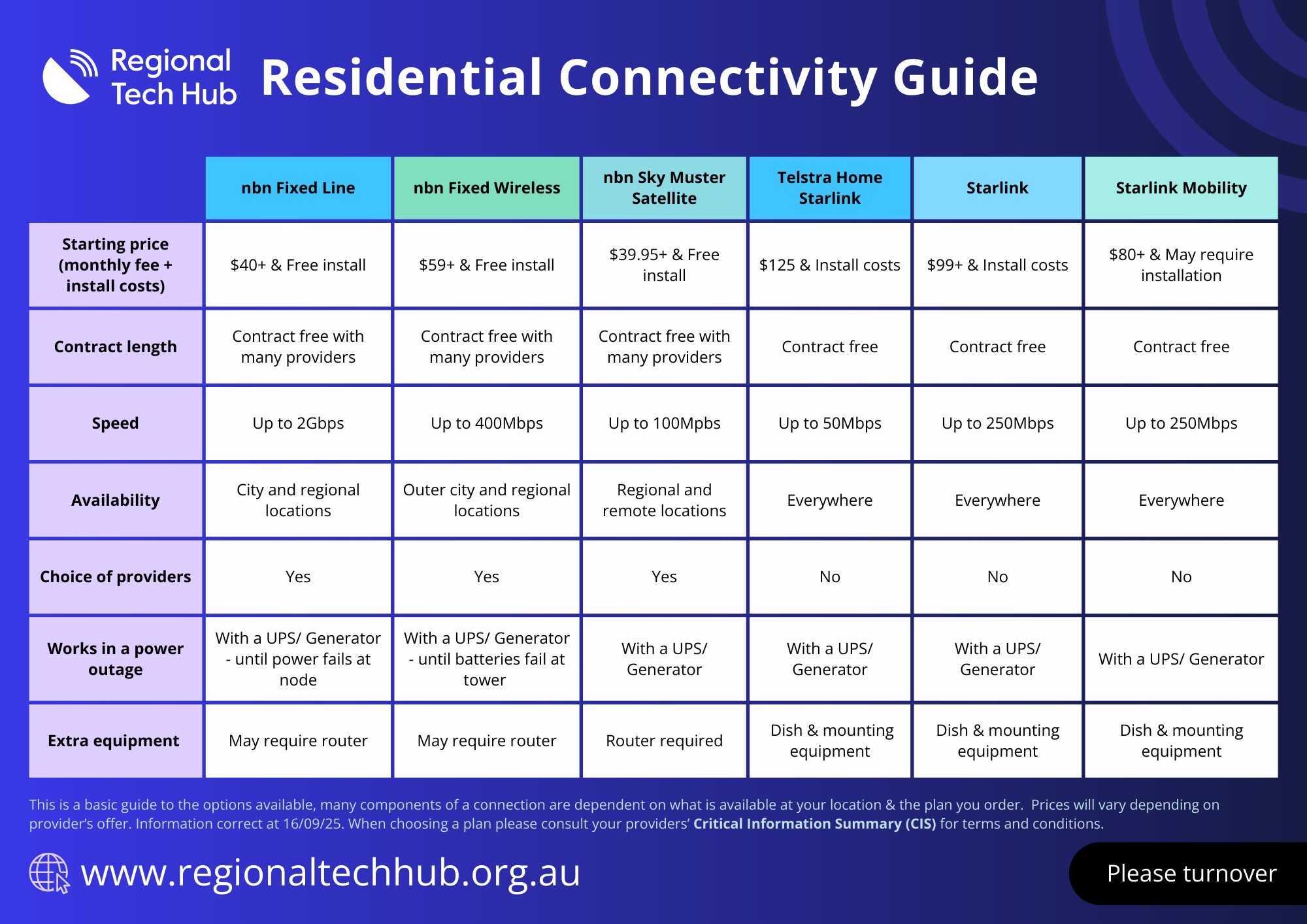
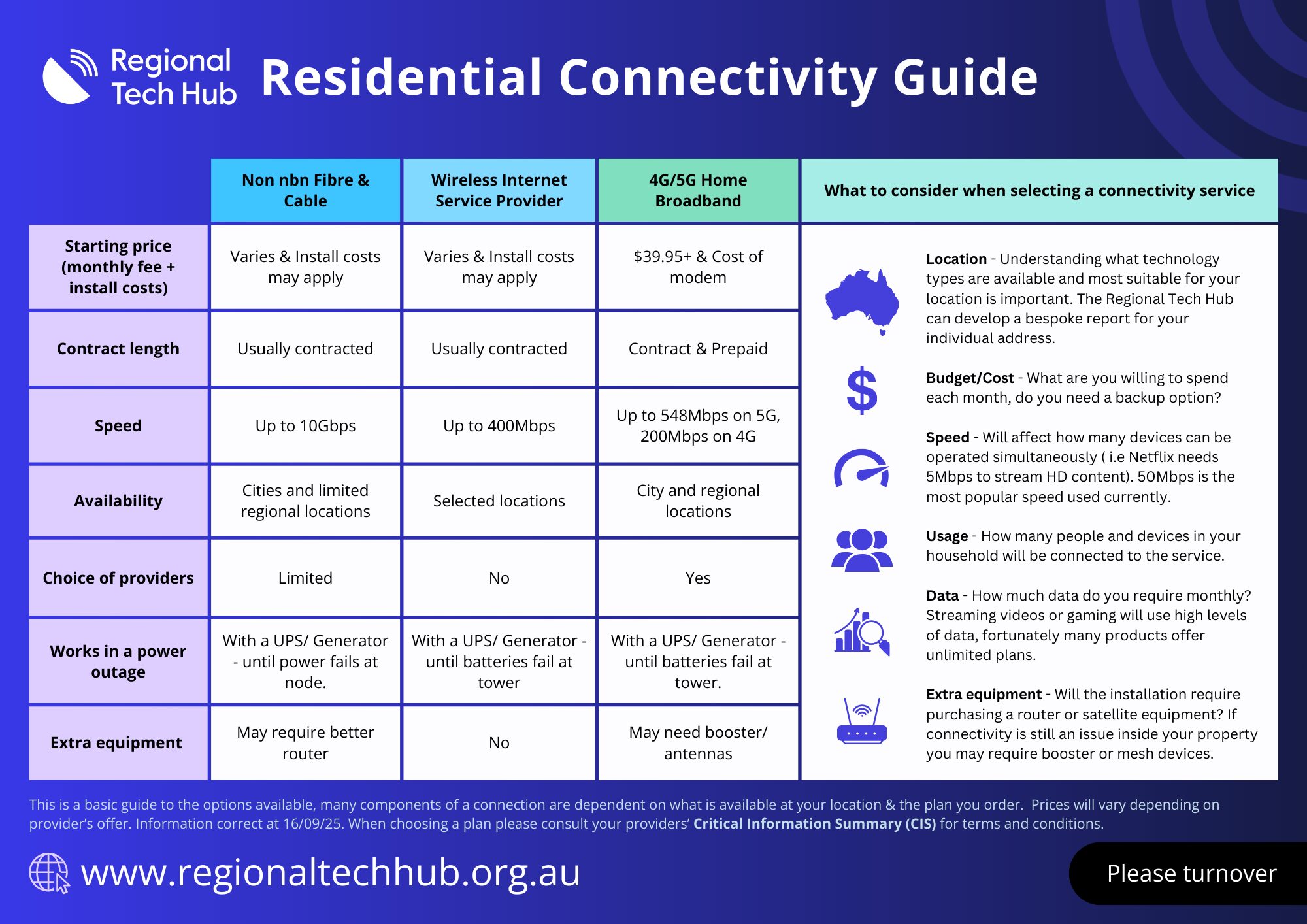
Learn more about what options best suit your needs
Internet options in regional, rural and remote Australia can be confusing, and there is a lot of misinformation about what is available. The following table has been designed to help you work out what options might suit your needs, based on budget, speed, latency, equipment, and contract length.
-
-
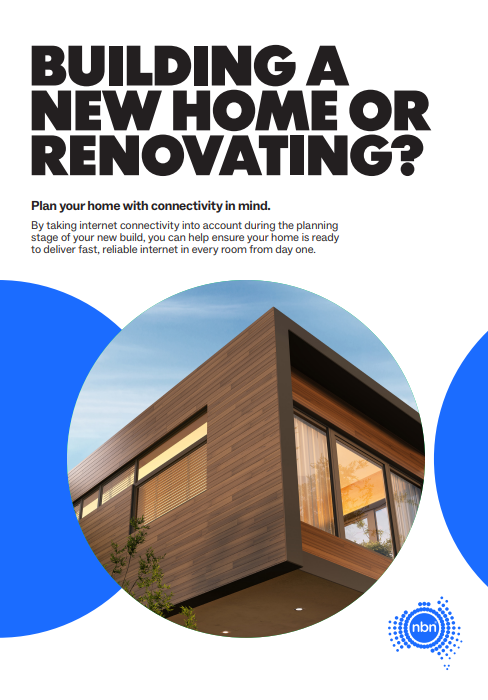
Building a new home?
If you’re building a new home or doing significant renovations to your current home, it pays to plan out your connectivity at the same time. It’s just as important as where to put the power points!
Check out this great resource from nbn® on how to add connectivity to your building plans.
-
Request a Connectivity Report
Request a free and independent connectivity report through the Regional Tech Hub to find out all your internet options tailored to your specific needs. The report takes into account factors such as budget, latency, speed, contract length, and equipment costs, ensuring you get the best possible solution for your circumstances. The report will help you make informed decision and find the most suitable and cost-effective internet service for your requirements.

-
Check out our most recent resources
-
Here to assist regional residents
-
-

We can help you understand all your phone and internet options, tailored to your needs. Our service is completely free and independent. Request a connectivity report to get started.
-

We can assist you with existing connectivity issues. Your first point of contact is your Retail Service Provider, however if it remains unresolved, we can escalate it for you.
-

We can speak with you at a time that suits you. Simply book an appointment with one of our team members, and we’ll ensure try and solve your connectivity issue.
-

We understand how frustrating network outages can be and are here to assist you. Check our outage information page to stay updated on current connectivity issues in your area.
-
-

Still having issues?
Chat to us on our hotline with one of our team members and let’s get the conversation started. If we don’t answer, we’ll get back to you in no time at all.
